|
|
Potential control restriction |
|
|
|
Navigation & Acknowledgements |
6 pictures on this page - scroll down to see the rest
cockpit module trial fit: 2008-09-13
Nikon Coolpix 8400
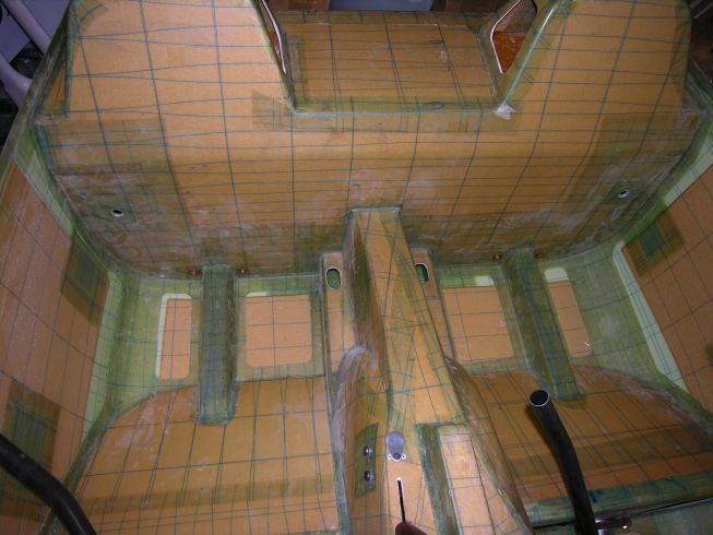
The cockpit module placed the lower fuselage moulding to do the check of stick movement as advised in the manual on page 13-10. If I don't sit in the cockpit module, all is fine and movement of the sticks is constrained only by the cockpit sides and tunnel. However, when I sit in it to check how the cranks in the sticks should be aligned between my knees, the movement is considerably reduced; beyond about 100mm deflection left or right from centre at the top of the stick, there's an unpleasant noise as the corners of CS07/08 touch against the fuselage floor. Note that the outlines of the brown foam inserts in the lower moulding don't seem to have any real relationship with the various cutouts and shapes of the cockpit module. I'd have thought that perhaps they would line up in places. There is not even lateral symmetry - the seats, on mine anyway, have slightly different shapes port and starboard.
fuselage lower moulding: 2008-09-13
Nikon Coolpix 8400
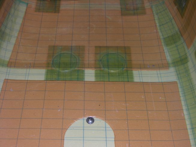
The cockpit flange at the bottom of the seat backrest is supported by only fresh air. It falls in the middle of the green area across the middle of this picture. Any pressure on the seat pan will bend the cockpit module down into that depression. That causes CS07/08 to touch the fuselage floor where small black marks may just be seen on the brown area at the rear of the green stripe
CS07/CS08 clearance: 2008-09-13
Nikon Coolpix 8400
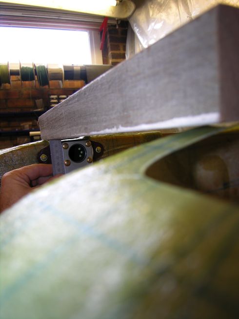
Checking that the clearance for CS07/08 is correct. Here it is 6mm; the manual calls for 5mm to 7mm.
depression in fuselage floor: 2008-09-22
Nikon Coolpix 8400
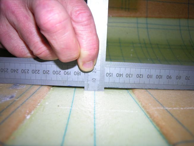
This picture shows that the depression in the green stripe (the non-foam area) of the fuselage floor is about 4mm deep. Thus if the cockpit module is pushed down into that locally the clearance for CS07/CS08 will be badly compromised.
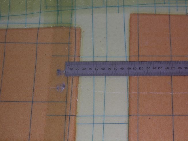
depression in fuselage floor: 2008-09-22
Nikon Coolpix 8400
This shows the width of the green depression (non-foam area) in the fuselage floor, with a ruler placed against the witness mark left by CS07/08 on the port side. The depression lies between about 25mm and 100mm forward of the witness mark.
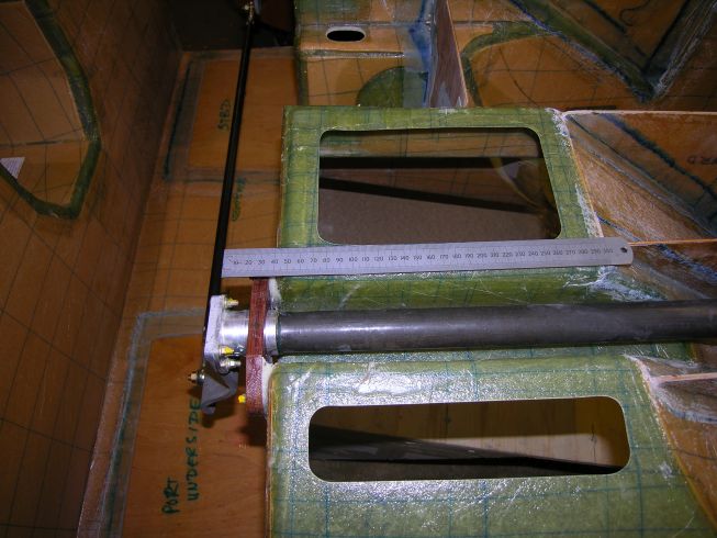
cockpit module seatback flange: 2008-09-22
Nikon Coolpix 8400
The same ruler as in the previous picture, positioned on the underside of the cockpit module with its end aligned with CS07. Note that the cockpit module flange at the bottom of the seatbacks falls between the 25mm mark and the 100mm mark, and thus is within the depressed area of the fuselage floor. When bonding in the cockpit module, care will need to be taken to ensure that no pressure is placed on this area to cause deflection and control binding.
|
|
|
go to next picture page |
|
|
||
| Return to Rowland's home page |
| This page last updated 2013-10-16. I try to make this page as accessible as possible, by adhering to HTML 4 standards. |
|
|
| I welcome comments on this website. However, because of the amount of spam it attracts, I no longer post a direct e-mail address on any page. Instead, please click here to contact me. You will have to confirm that you are human before the message will be sent on to me. | ||