|
|
Wing conduit installation |
|
|
|
Navigation & Acknowledgements |
6 pictures on this page - scroll down to see the rest
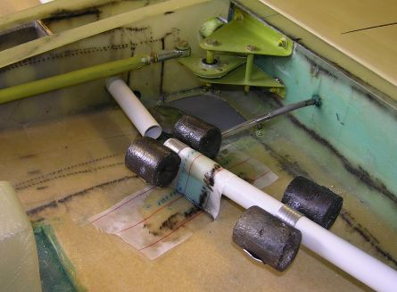
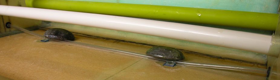
Wing conduit support installation: 2007-09-06.
Nikon Coolpix 8400
The inboard and outboard sections of the wing conduit during installation. The end of the outboard section of conduit is weighed down to ensure it stays firmly in contact with the foam pad while the BID strap over it cures.
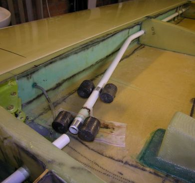
Outboard wing conduit installation: 2007-09-06.
Nikon Coolpix 8400
The outboard section of the wing conduit showing the bend, made before installation using a bending spring.
Wing conduit at inspection panel: 2007-09-07.
Nikon Coolpix 8400
The area between the inboard and outboard conduit sections after installation. The inspection panel at the top of the picture has its polycarbonate sheet cover fitted, but the protective film has not yet been removed from the polycarbonate. The stall-warner tube passes from the spar at upper right to the rib at upper left, held down in between to the lower wing skin by one of the BID clips. The gap between the inboard & outboard conduit allows for replacement of the flexible tubing to the stall-warner, should that ever become necessary.
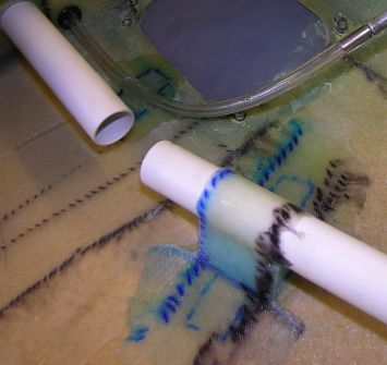
Wing conduit tip support layup: 2007-09-06.
Nikon Coolpix 8400
The BID straps laid up over the outboard end of the wing conduit with peel-ply on top. The blue and black "dotted lines" around the edges of the BID are the cutting marks made with a felt-tip pen, to ensure correct alignment with the weave. Not visible between the conduit and the spar at each strap location are flox pads to provide support for the BID. The number and size of BID straps is excessive merely to support the conduit and the expected weight of wiring inside it, but was deemed neessary for the situation when a rod will be inserted into the conduit and used as the wingtip support during future finishing operations. The conduit appears to pass right out through the tip moulding in this picture - see below for what's really going on.
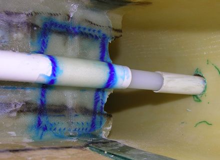
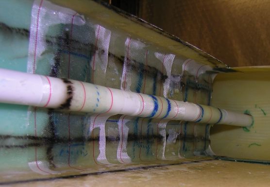
Wing conduit tip alignment: 2007-09-07.
Nikon Coolpix 8400
The outermost BID strap laid up over the outboard end of the wing conduit. The correct positioning of the conduit during cure was ensured by temporarily fitting a separate piece of conduit passing through the tip moulding, aligned with the fixed section by a piece of nylon rod fitted internally.
Bonding stall warner tube clips: 2007-09-06.
Nikon Coolpix 8400
Two of the BID clips securing the stall-warner tubing, weighed down while bonding to the lower wing skin with epoxy resin.
|
|
|
go to next picture page |
|
|
||
| Return to Rowland's home page |
| This page last updated 2013-10-16. I try to make this page as accessible as possible, by adhering to HTML 4 standards. |
|
|
| I welcome comments on this website. However, because of the amount of spam it attracts, I no longer post a direct e-mail address on any page. Instead, please click here to contact me. You will have to confirm that you are human before the message will be sent on to me. | ||